ROS 2 Camera Calibration
Preamble – The Why
Underlying many perception tasks is the need to express the pose of one coordinate frame relative to another and to compose such poses along kinematic and sensing chains. This allows us to take transform sensor obeservations from the reference frame of a sensing element. This is useful.
A rigid-body pose can be represented by a homogeneous transformation matrix, see here for more on that. \[\begin{equation} \mathbf{T}^{A}_{B} = \begin{bmatrix} \mathbf{R}^{A}_{B} & \mathbf{t}^{A}_{B} \\ \mathbf{0}^{\top} & 1 \end{bmatrix} \in SE(3), \qquad \mathbf{R}^{A}_{B} \in SO(3),\ \ \mathbf{t}^{A}_{B} \in \mathbb{R}^{3}, \label{eq:se3} \end{equation}\] Where \(\mathbf{R}^{A}_{B}\) is a \(3\times3\) rotation matrix belonging to the special orthogonal group \(SO(3)\) and \(\mathbf{t}^{A}_{B}\) is a translation vector.
But how do we find the values of the transformation for a real robot? We can use the CAD data if it is available but often that won’t be good enough for accurate manipulation. The problem becomes more acute if we are looking at perception sensor data with reading over longer ranges. Here we’’ll look at solving that problem using ROS industrial’s tools for the specific case of camera calibration.
The What
Camera calibration here will be defined through two sets of parameters, intrinsic and extrinsic. The intrinsic parameters define how observations in a 3D scene are projected onto the 2D image plane, accounting for the image sensor size, focal length, and principal point as defined by the pin-hole camera model. When the intrinsic parameters are applied to a raw camera image observation the produced result is a “rectified” image. The extrinsic parameters define where the camera sensor reference frame is within the world, through a 3D position and rotation (the transform we looked at earlier). This information is critical if you are trying to use the camera sensor data to make accurate spatial measurements.
Under the pinhole camera model, a world point \(\tilde{\mathbf{p}}^{W} = [\,X\ Y\ Z\ 1\,]^{\top}\) projects to homogeneous image coordinates \(\tilde{\mathbf{u}} = [\,u\ v\ 1\,]^{\top}\) through the \(3\times4\) projection matrix \(\mathbf{P}\), \[\begin{equation} \lambda\,\tilde{\mathbf{u}} = \mathbf{P}\,\tilde{\mathbf{p}}^{W} = \mathbf{K}\,[\,\mathbf{R}\ |\ \mathbf{t}\,]\,\tilde{\mathbf{p}}^{W}, \end{equation}\] where \(\lambda\) is a depth-dependent scale factor.
The intrinsic matrix \(\mathbf{K}\) collects the camera’s internal parameters and decomposes into a 2D translation (the principal point), a 2D scaling (the focal lengths), and a 2D shear, while the extrinsic matrix \([\,\mathbf{R}\ |\ \mathbf{t}\,]\) is the \(SE(3)\) pose of the world relative to the camera, comprising a 3D translation and a 3D rotation, so that the projection matrix decomposes in full as shown below.
\[\begin{equation} \mathbf{P} = \overbrace{ \underbrace{\begin{bmatrix} 1 & 0 & x_0 \\ 0 & 1 & y_0 \\ 0 & 0 & 1 \end{bmatrix}}_{\text{2D translation}} \underbrace{\begin{bmatrix} f_x & 0 & 0 \\ 0 & f_y & 0 \\ 0 & 0 & 1 \end{bmatrix}}_{\text{2D scaling}} \underbrace{\begin{bmatrix} 1 & s/f_x & 0 \\ 0 & 1 & 0 \\ 0 & 0 & 1 \end{bmatrix}}_{\text{2D shear}} }^{\textstyle \mathbf{K}} \overbrace{ \underbrace{\begin{bmatrix} \mathbf{I} & \mathbf{t} \end{bmatrix}}_{\text{3D translation}} \underbrace{\begin{bmatrix} \mathbf{R} & \mathbf{0} \\ \mathbf{0}^{\top} & 1 \end{bmatrix}}_{\text{3D rotation}} }^{\textstyle [\,\mathbf{R}\ |\ \mathbf{t}\,]} \end{equation}\]
Here \(f_x\) and \(f_y\) are the focal lengths in pixel units, \((x_0, y_0)\) is the principal point, and \(s\) is the skew, which is negligible for modern sensors, so that \(\mathbf{K}\) multiplies out to the familiar upper-triangular form \([\,f_x,\,s,\,x_0;\ 0,\,f_y,\,y_0;\ 0,\,0,\,1\,]\). Estimating \(\mathbf{K}\) (intrinsic calibration) and the rigid transform between camera and robot (extrinsic, or hand-eye, calibration) is a prerequisite for metric perception; standard procedures based on planar targets and on observing a known motion of the end effector recover these parameters. Often manufacturers will provide intrinsic calibration values as determined at the point of manufacture, or nominal intrinsics taken across a large manufactured sample size, however extrinsic parameters are often use case specific based on the physical installation of a given sensor.
Typically under ROS intrinsic parameters feed into an image_proc pipeline, which converts raw distorted frames into geometrically corrected, rectified images:
- the raw
- the rectified
ROS Industrial’s Implementation
ROS Industrial have implementations and GUI tools to solve for both the intrinsic and extrinsic parameters. Both calibrations use the Ceres Solver (non-linear least squares) to minimize reprojection residuals, rather than the classical closed-form algorithm approach (e.g., Tsai-Lenz) both problems are formulated as iterative bundle adjustment.
Camera Intrinsic Calibration
- Model: OpenCV pinhole camera + “plumb_bob” distortion (k1, k2, p1, p2, k3)
- Cost: minimizes 2D pixel reprojection error per target observation (camera_intrinsic_cost.h:21)
- This is functionally equivalent to Zhang’s method, but re-implemented via Ceres rather than calling cv::calibrateCamera
Extrinsic Hand-Eye Calibration
- Formulation: Simultaneous optimization of
camera_to_camera_mountandtarget_mount_to_targettransforms - Cost (2D3D): projects 3D target points through the full kinematic chain and minimizes pixel error
- Cost (3D3D): minimizes 3D Euclidean error directly
- This is a simultaneous/continuous optimization approach, not one of the classical batch hand-eye solvers
The How
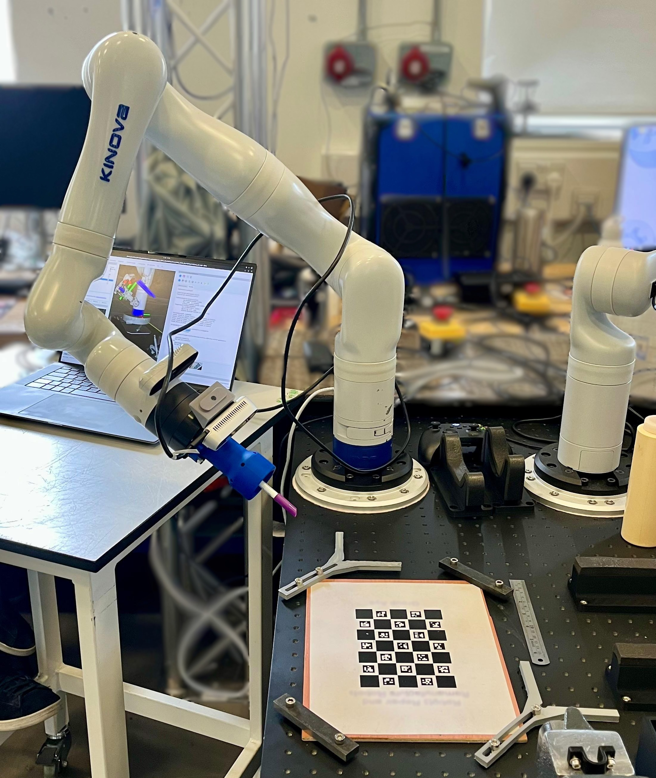
With the background covered, this section walks through the practical steps for running both calibrations using the industrial_calibration_ros2 package.
Below is an image of our setup using a 7 DoF Kinova Gen 3 arm along with a RealSense D435i. .
Prerequisites
As the TF transform information is required (
data_collection_nodeneedsbase_link→tool_frameTF to be publishing) you need to already have a robot model and state publisher setup.Install the packages and dependencies into your workspace
cd <workspace>/src
git clone https://github.com/ros-industrial/industrial_calibration_ros2
cd <workspace>
vcs import src < src/industrial_calibration_ros2/dependencies.repos
rosdep install --from-paths src -iry
colcon build- Prepare your ChArUco target board (here we used 7×5, 20mm squares, 12.7mm ArUco markers, DICT_4X4_250).
The data collection pipeline uses the same nodes in both the intrinsic and extrinsic cases, it connects three nodes in series.
Legend: ROS topic ROS node ROS service
Intrinsics
Walkthrough
See the official documentation for additional detail, but I struggled with it and wrote this so I don’t have to in future.
- Prepare your intrinsic configuration yaml file.
# ChArUco grid target finder
target_finder:
  type: CharucoGridTargetFinder
  rows: 7
  cols: 5
  chessboard_dim: 0.020
  aruco_marker_dim: 0.012727
  dictionary: 4  # DICT_4X4_250

intrinsics_guess:
  fx: 908.4622802734375
  fy: 906.7409057617188
  cx: 649.304931640625
  cy: 349.4989318847656

# Other parameters
homography_threshold: 2.0
use_extrinsic_guesses: true
use_opencv: false- Prepare your intrinsic launch file, the example below is based on this one
<?xml version="1.0" encoding="UTF-8"?>
<launch>
  <arg name="image_topic" default="/d435/camera/color/image_raw"/>
  <arg name="base_frame" default="kinova_base_link"/>
  <arg name="tool_frame" default="kinova_tool_frame"/>
  <arg name="save_path" default="/tmp/calibration"/>
  <arg name="config_file" default="$(find-pkg-share my_robot_description)/config/camera_cal/intrinsic_target_detector_config.yaml"/>
  <arg name="sync_time" default="1.0"/>

  <!-- Target detector node -->
  <node name="target_detector_node" pkg="industrial_calibration_ros" exec="industrial_calibration_ros_target_detector" output="screen">
    <remap from="image" to="$(var image_topic)"/>
    <param name="config_file" value="$(var config_file)"/>
  </node>

  <!-- Image trigger node -->
  <node name="image_trigger" pkg="industrial_calibration_ros" exec="image_trigger.py">
    <remap from="image" to="image_detected"/>
    <remap from="image_out" to="image_detected_trigger"/>
    <param name="sync_time" value="$(var sync_time)"/>
  </node>

  <!-- Data collector -->
  <node name="data_collection_node" pkg="industrial_calibration_ros" exec="data_collection_node.py" output="screen">
    <remap from="image" to="image_detected_trigger"/>
    <param name="base_frame" value="$(var base_frame)"/>
    <param name="tool_frame" value="$(var tool_frame)"/>
    <param name="save_path" value="$(var save_path)"/>
  </node>
</launch>- Run your launch file:
ros2 launch <your_pkg> <your_launch_file>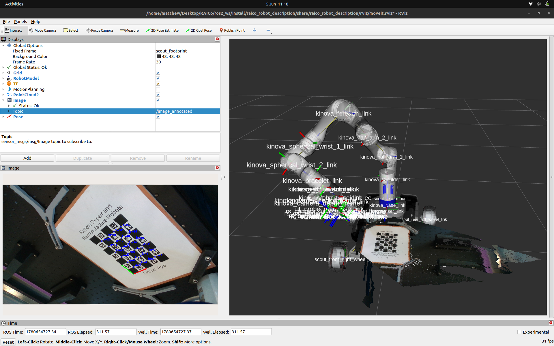
# ros2 launch my_robot_description intrinsic_cam_cal_data_collection.launch.xml- Verify the target detector is seeing the board by viewing
/image_annotatedin RViz orrqt_image_view.
For each capture position:
- move the robot/board to a new pose varying distance, tilt, and rotation for diverse coverage
- trigger a capture:
ros2 service call /trigger std_srvs/srv/Triggerimage_triggerchecks that the latest frame is no older thansync_timeand then forwards it toimage_detected_triggerwhere thedata_collection_nodepicks it up and looks up the transform fromkinova_base_link→kinova_tool_frameat that timestamp, and stores the image and pose pair in memory.
Repeat ~20–50 times with diverse poses.
Save the dataset:
ros2 service call /save std_srvs/srv/Trigger- This writes a timestamped directory to /tmp/calibration/YYYY-MM-DD_HH:MM:SS/ containing:
- images/0000.png, 0001.png, ...
- poses/0000.yaml, 0001.yaml, ... (TF translation + quaternion)
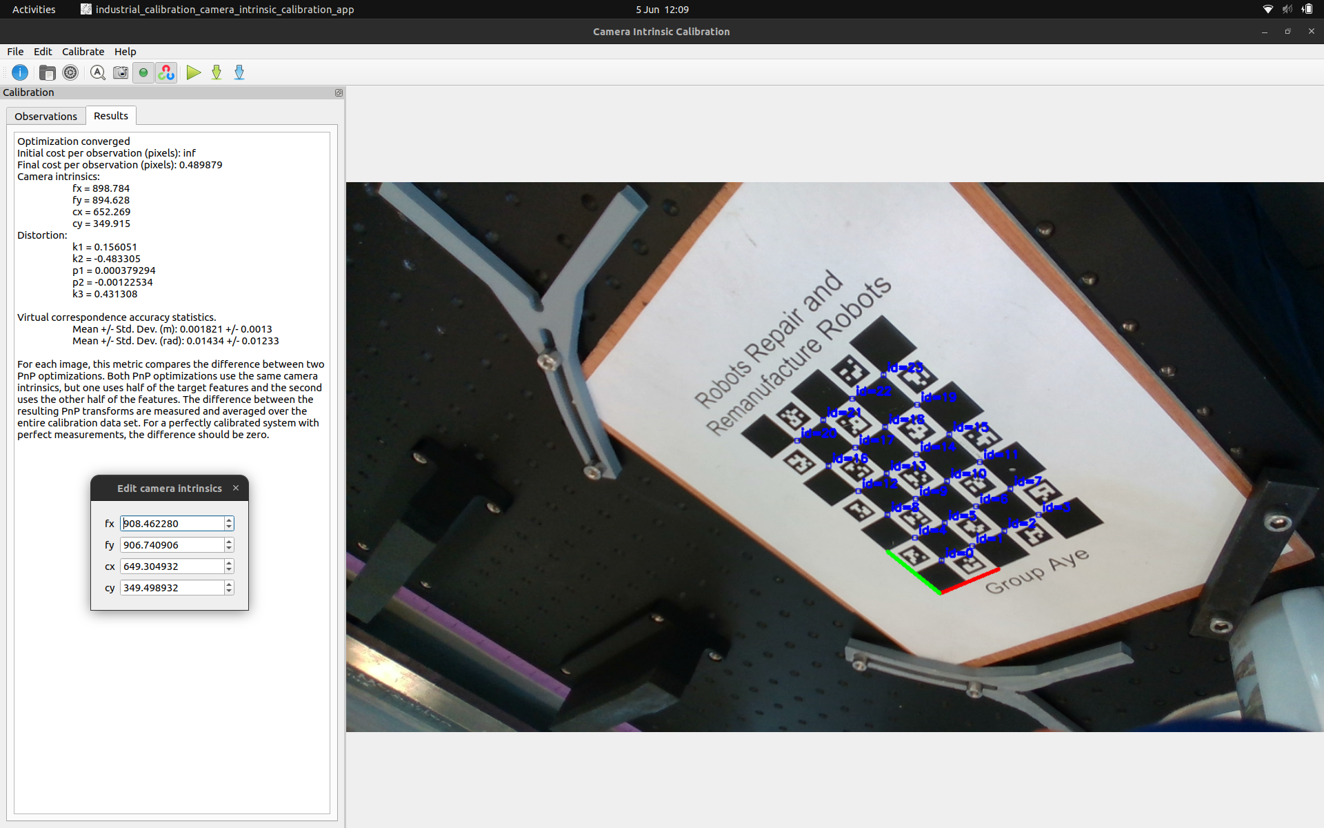
- cal_data.yaml: index linking each image to its pose- Run intrinsic calibration on the saved dataset. Launch the Camera Intrinsics Calibrator GUI, load
cal_data.yamland your configuration from step 1, then click Calibrate.
Results
Optimization converged
Initial cost per observation (pixels): inf
Final cost per observation (pixels): 0.489879
Camera intrinsics:
  fx = 898.784
  fy = 894.628
  cx = 652.269
  cy = 349.915
Distortion:
  k1 = 0.156051
  k2 = -0.483305
  p1 = 0.000379294
  p2 = -0.00122534
  k3 = 0.431308

Virtual correspondence accuracy statistics.
  Mean +/- Std. Dev. (m): 0.001821 +/- 0.0013
  Mean +/- Std. Dev. (rad): 0.01434 +/- 0.01233
Camera Intrinsics Calibrator GUI showing the optimised results and the detected ChArUco board.
It’s interesting to compare this to the nominal intrinsics RealSense provide for the D435i that was used for the intrinsics_guess in the config file.
intrinsics_guess:
  fx: 908.4622802734375
  fy: 906.7409057617188
  cx: 649.304931640625
  cy: 349.4989318847656
You can also export the intrinsic calibration results to a ROS friendly format.
camera_name: ""
image_height: 720
image_width: 1280
camera_matrix:
  rows: 3
  cols: 3
  data:
    - 898.78361383208119
    - 0
    - 652.26921337041949
    - 0
    - 894.62787909341966
    - 349.91461326315959
    - 0
    - 0
    - 1
distortion_model: plumb_bob
distortion_coefficients:
  rows: 1
  cols: 5
  data:
    - 0.15605068968761443
    - -0.48330472090155235
    - 0.00037929383928683616
    - -0.0012253364079995483
    - 0.43130799208530146
rectification_matrix:
  rows: 3
  cols: 3
  data:
    - 1
    - 0
    - 0
    - 0
    - 1
    - 0
    - 0
    - 0
    - 1
projection_matrix:
  rows: 3
  cols: 4
  data:
    - 898.78361383208119
    - 0
    - 652.26921337041949
    - 0
    - 0
    - 894.62787909341966
    - 349.91461326315959
    - 0
    - 0
    - 0
    - 1
    - 0
Extrinsics
Walkthrough
See the official documentation for additional detail and be sure to read the “Tips for Getting an Accurate Calibration”.
- Prepare your config file
# ChArUco grid target finder
target_finder:
  type: CharucoGridTargetFinder
  rows: 7
  cols: 5
  chessboard_dim: 0.020
  aruco_marker_dim: 0.012727
  dictionary: 4  # DICT_4X4_250

# Nominal
# intrinsics:
#   fx: 908.4622802734375
#   fy: 906.7409057617188
#   cx: 649.304931640625
#   cy: 349.4989318847656

# Calibrated
intrinsics:
  fx: 898.78361383208119
  fy: 894.62787909341966
  cx: 652.26921337041949
  cy: 349.91461326315959

camera_mount_to_camera_guess:
  x: 0.032303
  y: 0.001139
  z: 0.020307
  qx: -0.002568
  qy: 0.002100
  qz: 0.999932
  qw: -0.011183

target_mount_to_target_guess:
  x: 0.30
  y: 0.00
  z: 0.00
  qx: 0.00
  qy: 0.00
  qz: 0.00
  qw: 0.00

homography_threshold: 2.00
static_camera: false- Prepare your launch file
<?xml version="1.0" encoding="UTF-8"?>
<launch>
  <arg name="target_mount_frame" default="kinova_base_link"/>
  <arg name="target_frame" default="cal_target_frame"/>
  <arg name="camera_mount_frame" default="kinova_tool_frame"/>
  <arg name="camera_frame" default="rs_camera_1_color_optical_frame"/>
  <arg name="save_path" default="/tmp/calibration"/>
  <arg name="config_file" default="$(find-pkg-share my_robot_description)/config/camera_cal/extrinsic_target_detector_config.yaml"/>
  <arg name="sync_time" default="2.0"/>
  <!-- <arg name="image_topic" default="/d435/camera/color/image_raw"/> -->
  <arg name="image_topic" default="/d435/camera/color/image_rect"/>
  <arg name="static_camera" default="false"/>
  <arg name="headless" default="false"/>

  <!-- Static camera case -->
  <let name="base_frame" value="$(var camera_mount_frame)" if="$(var static_camera)"/>
  <let name="tool_frame" value="$(var target_mount_frame)" if="$(var static_camera)"/>
  <!-- Moving camera case-->
  <let name="base_frame" value="$(var target_mount_frame)" unless="$(var static_camera)"/>
  <let name="tool_frame" value="$(var camera_mount_frame)" unless="$(var static_camera)"/>

  <!-- Target detector node -->
  <node name="target_detector_node" pkg="industrial_calibration_ros" exec="industrial_calibration_ros_target_detector" output="screen">
    <param name="config_file" value="$(var config_file)"/>
    <remap from="image" to="$(var image_topic)"/>
  </node>

  <!-- Image trigger node-->
  <node name="image_trigger" pkg="industrial_calibration_ros" exec="image_trigger.py">
    <param name="sync_time" value="$(var sync_time)"/>
    <remap from="image" to="image_detected"/>
    <remap from="image_out" to="image_detected_trigger"/>
  </node>

  <!-- Data collector -->
  <node name="data_collection_node" pkg="industrial_calibration_ros" exec="data_collection_node.py" output="screen">
    <param name="base_frame" value="$(var base_frame)"/>
    <param name="tool_frame" value="$(var tool_frame)"/>
    <param name="save_path" value="$(var save_path)"/>
    <remap from="image" to="image_detected_trigger"/>
  </node>

  <!-- Rviz -->
  <group unless="$(var headless)">
    <node pkg="rviz2" exec="rviz2" args="-d $(find-pkg-share my_robot_description)/rviz/cam_cal.rviz">
      <param name="camera_mount_frame" value="$(var camera_mount_frame)"/>
      <param name="camera_frame" value="$(var camera_frame)"/>
      <param name="target_mount_frame" value="$(var target_mount_frame)"/>
      <param name="target_frame" value="$(var target_frame)"/>
    </node>
  </group>
</launch>- Run your launch file:
ros2 launch <your_pkg> <your_launch_file>
# ros2 launch my_robot_description extrinsic_cam_cal_data_collection.launch.xml
The ExtrinsicHandEyeCalibration RViz panel will appear alongside your robot model and the live camera feed with target detections overlaid.
RViz with the ExtrinsicHandEyeCalibration panel ready to collect observations.
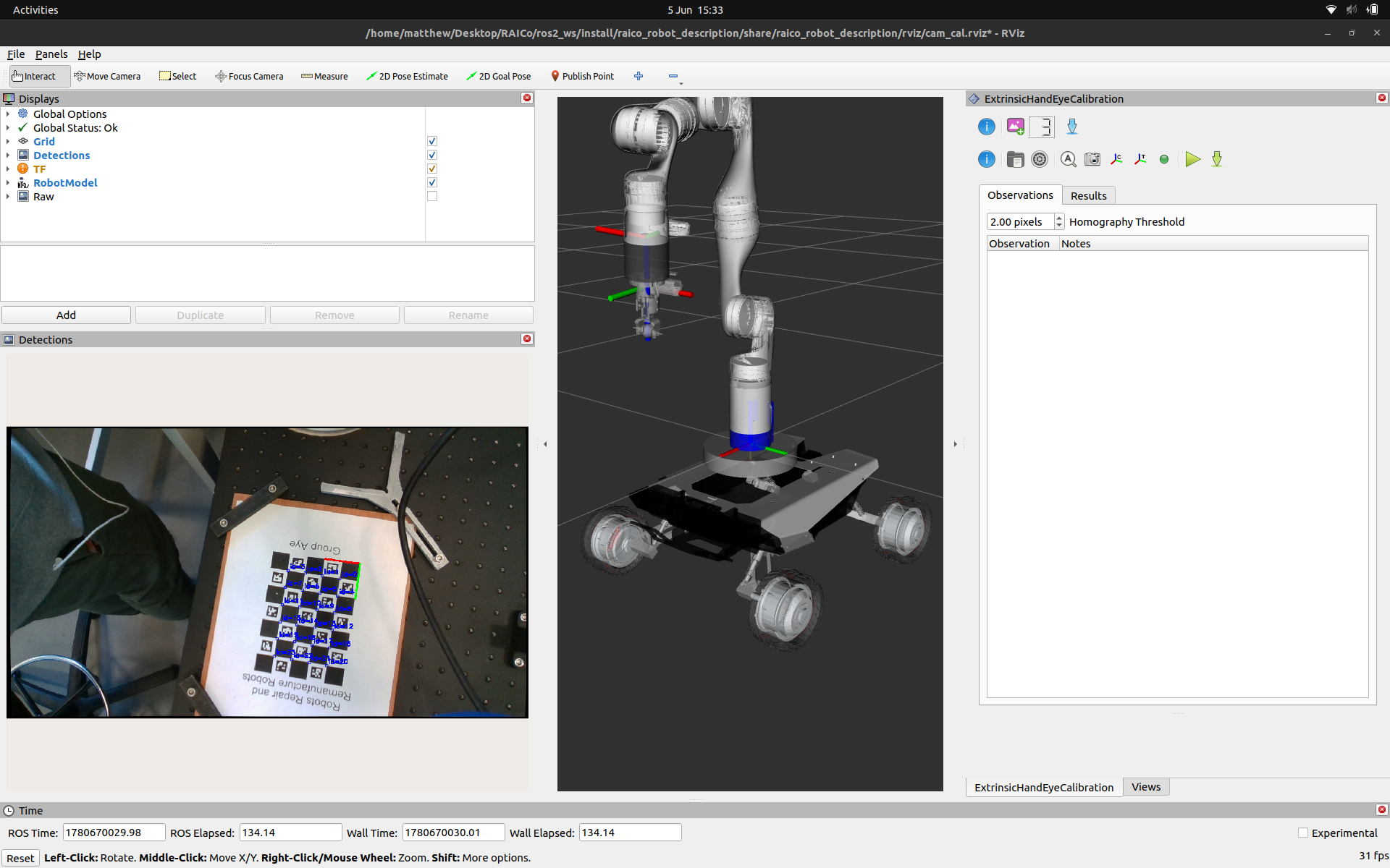
The
ExtrinsicHandEyeCalibrationpanel provides Trigger and Save buttons that call the same/triggerand/saveservices used in the intrinsics walkthrough, so no separate terminal calls are needed. Note that the launch file is configured to subscribe to the rectified image topic (/d435/camera/color/image_rect) — publishing your intrinsic calibration viaimage_procbeforehand will give the target detector cleaner input. Gather ~20–50 observations, varying end-effector distance, tilt, and rotation for good coverage:Once the dataset is gathered click Save. Then load the dataset and configuration into the extrinsic calibration panel.
Click Calibrate.
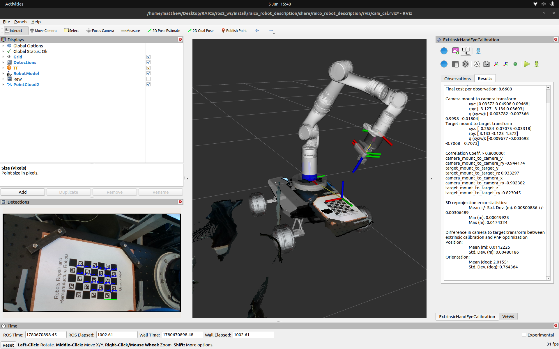
Results
If the optimisation converges you will get an output similar to that shown below, with the camera_mount_to_camera and target_mount_to_target transforms alongside several statistics measuring the quality and consistency of the solution across the dataset.
Checkout the “Evaluating the Results” section from the docs.
The results given here show high correlation coefficients > 0.8 indicating that we need to collect more distinct variety in the camera poses used in this calibration.
Optimization converged

Initial cost per observation: 85.3916
Final cost per observation: 8.6608

Camera mount to camera transform
  xyz: [0.03572 0.04908 0.09468]
  rpy: [  3.127   3.134 0.03603]
  q (xyzw): [-0.003782 -0.007366    0.9998  -0.01804]
Target mount to target transform
  xyz: [  0.2584  0.07075 -0.03318]
  rpy: [ 3.133 -3.123  1.572]
  q (xyzw): [-0.009677 -0.003698   -0.7068    0.7073]

Correlation Coeff. > 0.800000:
camera_mount_to_camera_y camera_mount_to_camera_ry -0.944174
target_mount_to_target_y target_mount_to_target_rz 0.933297
camera_mount_to_camera_x camera_mount_to_camera_rx -0.902382
target_mount_to_target_z target_mount_to_target_ry -0.823045

3D reprojection error statistics:
  Mean +/- Std. Dev. (m): 0.00500886 +/- 0.00306489
  Min (m): 0.00019923
  Max (m): 0.0174324

Difference in camera to target transform between extrinsic calibration and PnP optimization
Position:
  Mean (m): 0.0112225
  Std. Dev. (m): 0.00480186
Orientation:
  Mean (deg): 2.01551
  Std. Dev. (deg): 0.764364
ExtrinsicHandEyeCalibration panel showing the Results tab after a successful optimisation.
The calibrated camera_mount_to_camera transform needs to be back-propagated through the known kinematic chain to produce a corrected <origin> tag for the relevant URDF joint. This utility script automates that: given the calibrated and nominal optical frame names and the URDF joint’s parent/child frames, it outputs corrected xyz and rpy values ready to paste into your URDF or xacro file.
ros2 run realsense_launch compute_urdf_extrinsic.py --ros-args \
      -p nominal_frame:=rs_camera_1_color_optical_frame \
      -p calibrated_frame:=rs_camera_1_color_optical_frame_calibrated \
      -p joint_parent_frame:=ut_probe_realsense_link \
      -p joint_child_frame:=rs_camera_1_bottom_screw_frame
======================================================================
Corrected URDF <origin> for:
Joint parent : ut_probe_realsense_link
Joint child : rs_camera_1_bottom_screw_frame
Calibration : rs_camera_1_color_optical_frame → rs_camera_1_color_optical_frame_calibrated
Copy this line into your URDF / xacro:
<origin xyz="0.00361 -0.01539 0.01290" rpy="0.12208 -1.55175 -1.67910"/>
Individual values:
x=0.003614 y=-0.015389 z=0.012902
roll=0.122082 pitch=-1.551747 yaw=-1.679101
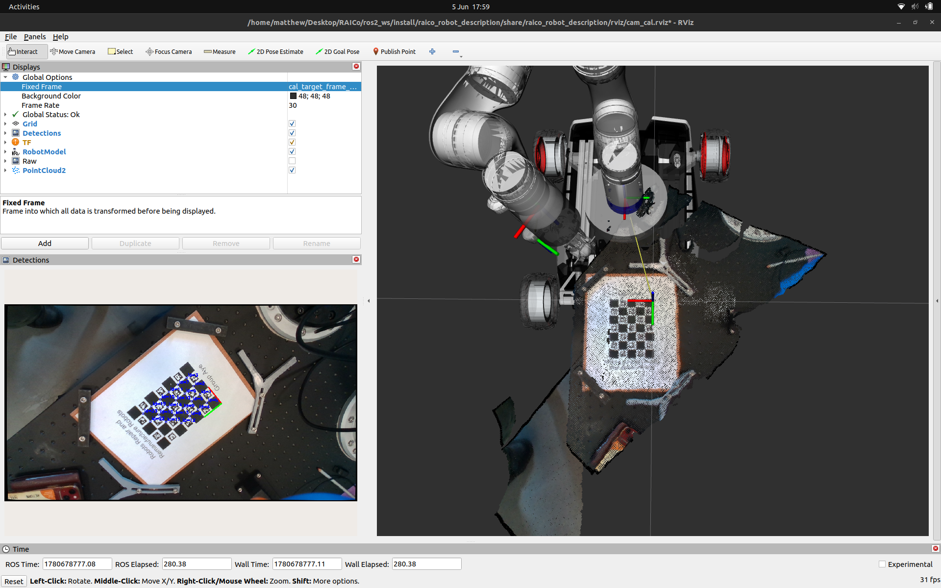
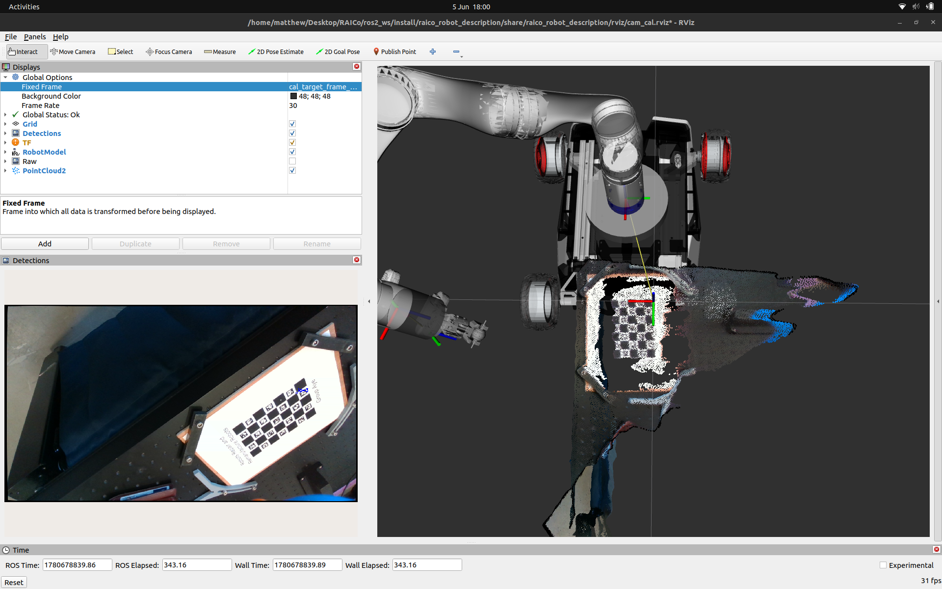
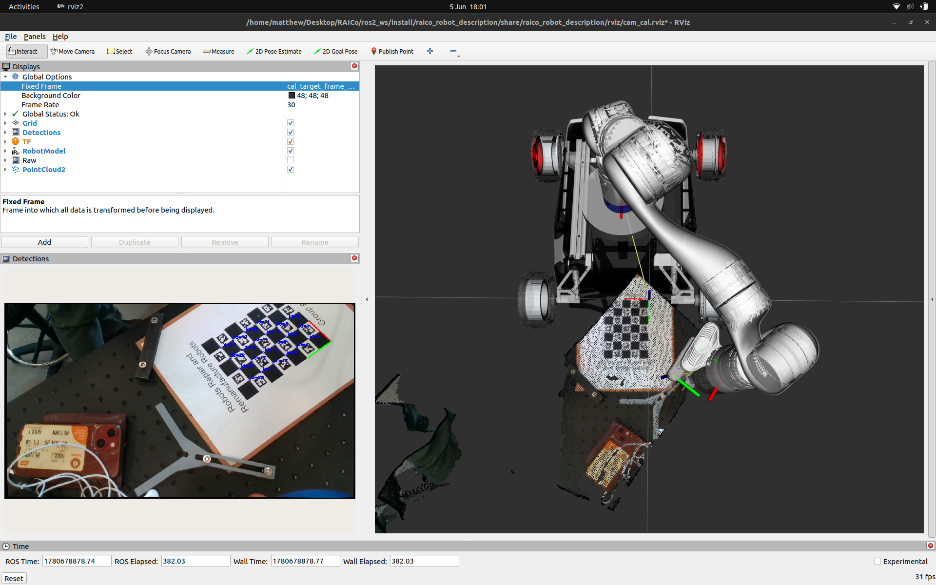
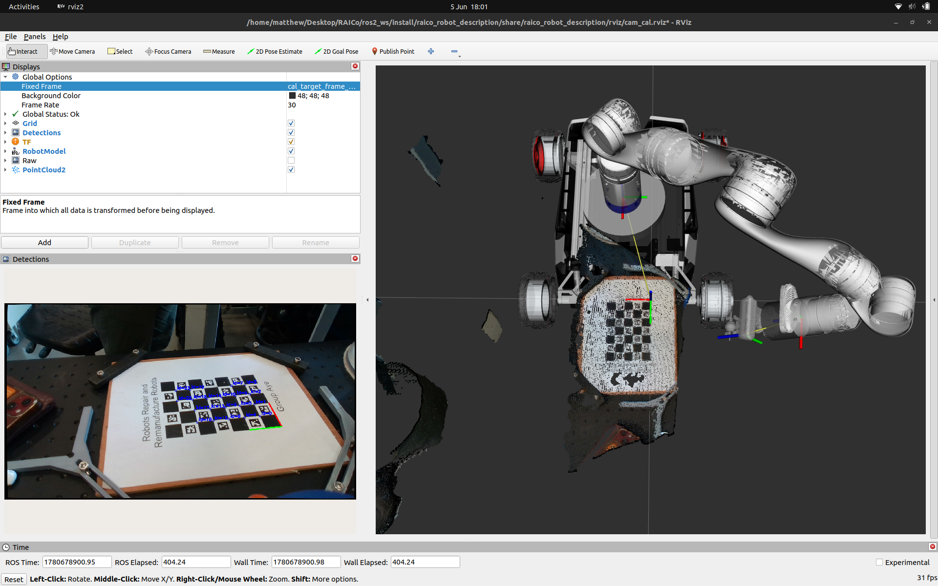
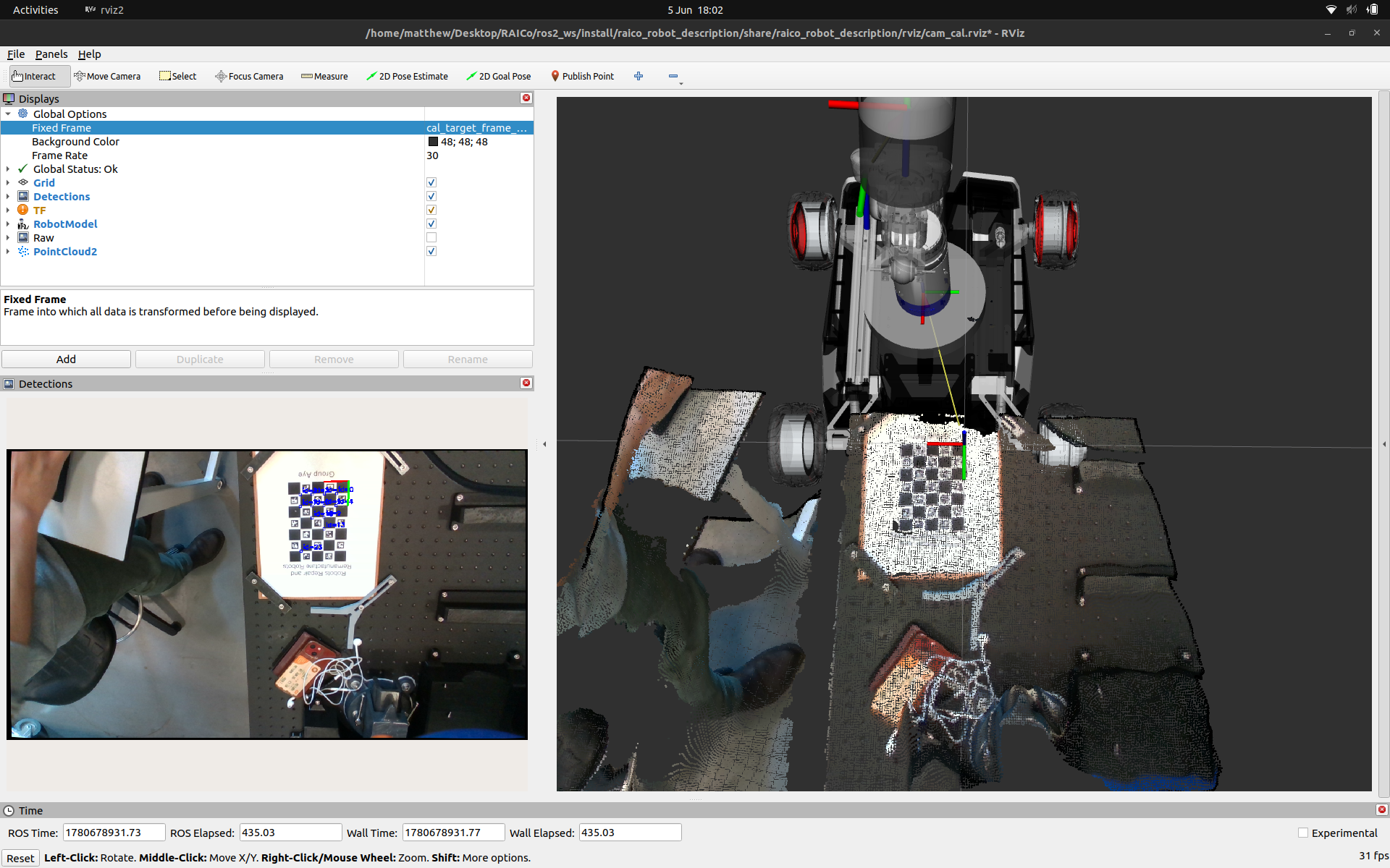
======================================================================Once applied you can test the calibration in a number of ways. Here we are using the point cloud output from the RealSense’s depth data as a form of verification at several different manipulator configurations.
Resources and Further Reading
- ROS image_proc Wiki
- ROS Industrial Intrinsic Calibration Docs
- ROS Industrial Extrinsic Calibration Docs
- Ceres Solver
- Zhang, Z. (2000). A flexible new technique for camera calibration
- OpenCV calib3d module documentation
- Shah, M. (2013). Solving the robot-world/hand-eye calibration problem using the Kronecker product.
- Tsai, R. Y., & Lenz, R. K. (1989). A new technique for fully autonomous and efficient 3D robotics hand/eye calibration.
Hey you!
Found this useful or interesting?
Consider donating to support.
Any question, comments, corrections or suggestions?
Reach out on the social links below through the buttons.